


Search by shape, function & use


Regardless of the type of resistor, poor heat dissipation is a major cause of failure. In recent years, electrical equipment has become smaller, more densely packed, and the environment in which it is used has become hotter, making the thermal design of the entire substrate an important issue.
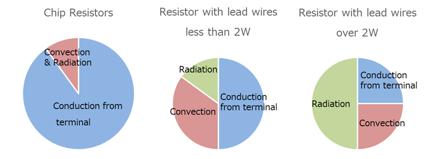
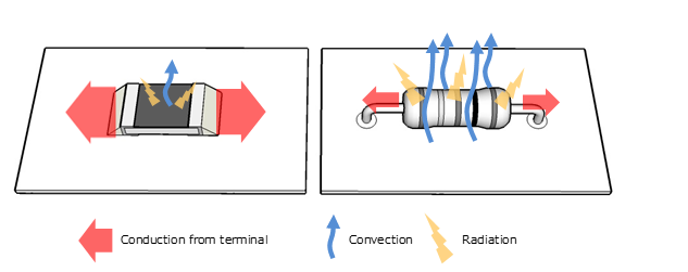
The graph and diagram below are images of heat dissipation from a resistor at room temperature.
Lead-type resistors have thin and long lead wires (terminals), so they have high thermal resistance and do not dissipate heat very well.
Conversely, the ratio of convection and radiation is high because the area of the resistor body is large.
On the other hand, since the surface area of chip resistors is small, convection and radiation are difficult to occur, and approximately 90% of the resistance is conducted through the terminals.
Chip Resistor Resistor with lead wires
Heat dissipation characteristics vary depending on the shape. Even when using parts with the same power rating, it is necessary to thoroughly verify substrate heat resistance etc. depending on the shape.

Glossary
|
■ Conduction from terminal ■ Convection ■ Radiation Materials with a temperature higher than absolute zero (-273℃) emit infrared rays. |
Chip resistor 6332mm Resistor with lead wires (6mm off the substrate)
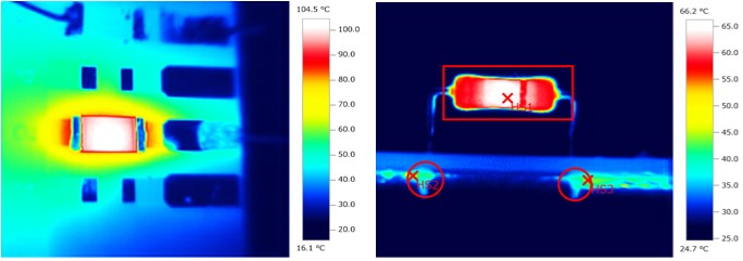
Ambient temperature: 25℃ Load factor 1W
Even for resistors with the same power rating, chip resistors have a high rate of heat conduction from the terminal to the substrate pattern, and the difference in temperature between the component body and the substrate temperature (near the terminal) is smaller than that of resistors with lead-wires.
When changing the design from a resistor with lead wires to a chip resistor, it is necessary to verify the heat resistance of the substrate.
【Reference data】Thermal conductivity of materials
| Materials | Thermal conductivity [W/m・K] | Remark |
| Copper | 377 | Substrate patterns,lead-wires of resistors etc. |
| Aluminum | 206 | |
| Iron | 67 | |
| Solder(Sn-Ag-Cu系) | 60 | Materialsused to join parts |
| Air | 0.024 | |
| Paper phenol(FR-2) | 0.13-0.25 | Substrate material |
| Glass epoxy(FR-4) | 0.25-0.45 | Substrate material |
By efficiently conducting heat through the substrate pattern (copper), which has high thermal conductivity, the temperature of the parts decreases.
*However, it must be noted that the substrate temperature will increase.
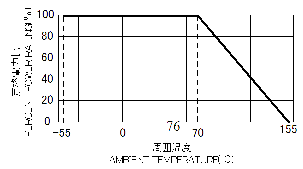
There is a general concept of limiting the load factor that can be applied to a resistor depending on the ambient temperature, and this condition is specified by a diagram called a power derating curve.
This is a specification to prevent the temperature of the resistor, which is a heat-generating component, from exceeding the temperature limit of the component, as the temperature rises (ΔT degrees) according to the ambient temperature + load factor.
Power derating curve (example)
When using resistors, no problems will occur if there is sufficient margin for power and temperature.
However, in recent years, electronic devices have become smaller, and components have become more densely mounted, so even if the ambience temperature and load factor to the resistor are the same, the margin may become smaller due to temperature interference between components. Therefore, when designing miniaturization and high-density packaging, it is necessary to take design consideration such as taking more power margins.
Examples of safety measures when designing circuits using resistors are shown below.
・【Component temperature control】Enlarge the land pattern on which the resistor is mounted
・【Component temperature control】Widen or thicken the pattern connected to the land
・【Component temperature control】Use parts larger than the actual power
・【Component temperature control】Use parts with heat dissipation measures
→ (Example) CPR High Power Thick Film Chip Resistors
・【Substrate heat resistance measures】It must be noted that chip resistors conduct more heat to
the substrate than resistors with lead-wires.
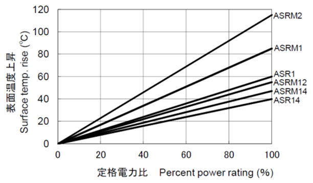
We also have temperature rise data for the parts of each product.
Please feel free to contact us as this data is useful as a reference for your design.
Example of component surface temperature rise (ΔT) data (ASR/ASRM Special Power Type Anti Surge Resistors)
References
Electronic component technology roadmap until 2024/JEITA
Guidelines for precautions when using fixed resistors for electronic equipment/JEITA
